wiring together ccfl lightsPost Date: 2012-07-01 |
Post Reply 
|
| Author | |
tju76 
Senior Member 

Joined: 06 Mar 2012 Online Status: Offline Posts: 804 |
 Quote Reply Quote Reply
 Topic: wiring together ccfl lights Topic: wiring together ccfl lightsPosted: 01 Jul 2012 at 8:53am |
|
hey guys went ahead and bought 3 extra ccfl tubes in addition to the 2 that came from ds i have them all wired up individually with three inverters, how can i have all lights run off of a single pci backplate on/off switch? is it just a matter of removing the wires that come out of the pci backplate on off switches?
|
|
|
|
 |
|
|
FrankW
DS Veteran 
Joined: 22 Feb 2010 Online Status: Offline Posts: 2254 |
Quote Reply
Posted: 01 Jul 2012 at 9:39am |
|
Hi tju76,
Take a look at this kit at Lampton I see that you all ready have the tubes but you can probably buy the switch and molex plug separate. Check out the video lower on the page. It shows just what you want to do. The switch has to go on the drop side of the inverter. If you have separate inverters you will have to gang wire the power leads into the inverters and run the common lead through the switch. Frank Edited by FrankW - 01 Jul 2012 at 1:25pm |
|
|
|
|
tju76
Senior Member
Joined: 06 Mar 2012 Online Status: Offline Posts: 804 |
Quote Reply
Posted: 01 Jul 2012 at 1:14pm |
|
i guess a better question was how to i go about gang wiring the ccfl tubes together so they all run on one pci switch,
|
|
|
|
|
|
|
|
FrankW
DS Veteran
Joined: 22 Feb 2010 Online Status: Offline Posts: 2254 |
Quote Reply
Posted: 01 Jul 2012 at 2:15pm |
|
tju76, the best way to do this is to buy the kit I showed you. I don't know what kind of inverters you have and what kind of connectors are on the inverters. Have you looked at the one that came on your computer and wired by DS. That is how you want to do it.
Basically you will get 12v and ground from the power supply. From the inverters you wire the switch wire to the switch. The other side of the inverters goes to the tubes. Newegg has a bunch of different Molex and other wiring harness like 1 male Molex wired to 4 female Molex connectors. This will work if your inverters have Molex connectors wired to them. Since you have to ask the question I think you would be a lot better off with the kit I showed you for sure. Look at this site. It gives instructions on what you need to do. Instructions You need to realize that I don't know what inverter or tubes you have and I assume no responsibility if you damage your computer or yourself. Frank Edited by FrankW - 03 Jul 2012 at 8:20am |
|
|
|
|
tju76
Senior Member
Joined: 06 Mar 2012 Online Status: Offline Posts: 804 |
Quote Reply
Posted: 01 Jul 2012 at 2:36pm |
|
i have these http://www.frozencpu.com/cat/l3/g6/c75/s134/list/p1/Lighting-Cold_Cathode_-_Kits-15_Single_CCFL-Page1.html they are powered by molex connectors each "kit" comes with 2 molex connections and a pci bracket
|
|
|
|
|
|
|
|
tju76
Senior Member
Joined: 06 Mar 2012 Online Status: Offline Posts: 804 |
Quote Reply
Posted: 01 Jul 2012 at 2:38pm |
|
i already have the lights wired up running etc my question was because i want to get sound activated inverters and i am sure there is a way to have them all run off of one pci bracket on/off switch
|
|
|
|
|
|
|
|
FrankW
DS Veteran
Joined: 22 Feb 2010 Online Status: Offline Posts: 2254 |
Quote Reply
Posted: 02 Jul 2012 at 6:48am |
|
The inverters you have power two lights each. I can't find a diagram but here are some thoughts.
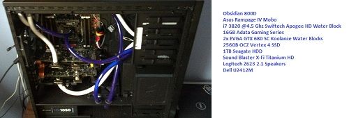
1. Wire two lights to one inverter and that will light two lamps with the same switch. Just remove the third inverter and wiring. 2. So that gives you two inverters wired to the power supply with Molex connectors. One inverter has two bulbs and one has one bulb. Remove the wire that wires to one of the two switches and wire it to the other switch. You need to connect it just like the wire you are connecting to. They may be color coded. This assumes that the yellow pair I see in the picture is wired to the switch. The switch just closes a loop that operates the inverter. It doesn't power the bulbs. So now you should have two inverters wired to the power supply. One inverter should have two bulbs and one inverter should have one bulb. The yellow wire from both inverters are wired to a single switch. You should have removed one inverter and two switch plates. Frank |
|
|
|
|
xii
Senior Member
Joined: 25 Feb 2012 Online Status: Offline Posts: 975 |
Quote Reply
Posted: 02 Jul 2012 at 12:19pm |
|
I am so unintelligent that my head hurts from reading all of that.
What does all those above mean in Xii words? |
|
|
|
|
FrankW
DS Veteran
Joined: 22 Feb 2010 Online Status: Offline Posts: 2254 |
Quote Reply
Posted: 02 Jul 2012 at 1:13pm |
|
I don't know if I can make it simpler.
1. Don't you have three inverters? 2. Don't the inverters have a yellow lead that runs to the switch plate? 3. Don't you have a cable coming from the inverter that is plugged into the power supply? 4. Don't your inverters look like the picture below that you referenced? The inverter has two output jacks for two separate bulbs. Is all of the above correct? Frank  Edited by FrankW - 02 Jul 2012 at 1:16pm |
|
|
|
|
tju76
Senior Member
Joined: 06 Mar 2012 Online Status: Offline Posts: 804 |
Quote Reply
Posted: 02 Jul 2012 at 2:39pm |
|
yes to all questions it will just be easier if i get to lamptrons i guess
|
|
|
|
|
|
|
|
FrankW
DS Veteran
Joined: 22 Feb 2010 Online Status: Offline Posts: 2254 |
Quote Reply
Posted: 02 Jul 2012 at 3:15pm |
|
Don't give up yet. It is hard for someone who has never done wiring before.
So you told me you have three inverters already wired. If that is true then you have one bulb powered from each of the three inverters, is that correct? You should also have three new back plates mounted with a on/off switch for each of the inverters. The wire going to each switch is yellow. Is all of that correct? Frank |
|
|
|
|
tju76
Senior Member
Joined: 06 Mar 2012 Online Status: Offline Posts: 804 |
Quote Reply
Posted: 02 Jul 2012 at 4:01pm |
|
all 3 inverters are full i have a total of 5 ccfl tubes, i have the original pci backplate from ds and a sound activated one for a 15 inch tube, the 3rd inverter i removed the switch from the pci bracket and placed it in the back of the case. but yes the switches have a red and yellow wires going out from them. what i want to do is beable to control all lights from one switch at most two. i am going to be replacing my 2 non sound activated modules with sound activated ones and the pci switch in the back is not able to be removed.
|
|
|
|
|
|
|
|
tju76
Senior Member
Joined: 06 Mar 2012 Online Status: Offline Posts: 804 |
Quote Reply
Posted: 02 Jul 2012 at 4:02pm |
|
thank you so much frank you are helping me alot
|
|
|
|
|
|
|
|
FrankW
DS Veteran
Joined: 22 Feb 2010 Online Status: Offline Posts: 2254 |
Quote Reply
Posted: 02 Jul 2012 at 5:00pm |
|
OK, I think we can do this now. The only possible problem is what effect the voice activation might have with the switch. That will probably take care of its self.
1. Take one back plate with the switch you want to control all of the lights from. Lets call that switch 1. 2. Remove the red and yellow wires from another switch and wire them directly to switch 1. Put the red wire on the red wire and the yellow wire to the yellow wire. Look at the existing wire and see if it is wrapped around the terminal or if the terminal has a hole through it. If it has a hole then you need to melt the solder in the hole and poke a pointed toothpick through the hole so there is enough room to insert the other wires. For safety sake remove the switch plate from the computer and work on it behind the case. Don't re-solder at this time. 3. Now remove the red and yellow leads from the next switch plate and wire them to switch 1 just like you just did. Now solder the leads and you should be operating all of the lights from one switch. 5. Remove the other switches and replace switch plate 1 back into the computer. You should now be done. If this doesn't make sense to you I suggest you take your computer to a local shop and pay them to do the wiring. It should only take a few minutes. Frank Edited by FrankW - 03 Jul 2012 at 8:18am |
|
|
|
|
tju76
Senior Member
Joined: 06 Mar 2012 Online Status: Offline Posts: 804 |
Quote Reply
Posted: 02 Jul 2012 at 5:37pm |
|
okay thank you very much i will work on this tommorow and tell you how it goes
|
|
|
|
|
|
|
|
tju76
Senior Member
Joined: 06 Mar 2012 Online Status: Offline Posts: 804 |
Quote Reply
Posted: 02 Jul 2012 at 5:38pm |
|
yeah there is a computer repair shop in town i might see if they can do it, they would actually come to the house too, even though they are like 5 mins up the road just a pain moving the case around
|
|
|
|
|
|
|
|
FrankW
DS Veteran
Joined: 22 Feb 2010 Online Status: Offline Posts: 2254 |
Quote Reply
Posted: 03 Jul 2012 at 8:24am |
|
Let me know how ever it works out.
Frank |
|
|
|
|
tju76
Senior Member
Joined: 06 Mar 2012 Online Status: Offline Posts: 804 |
Quote Reply
Posted: 03 Jul 2012 at 12:59pm |
|
one more question its not a problem if i need to use wire strippers to get to the actual wire because all i see is sleeving going to a terminal on "switch 1"
|
|
|
|
|
|
|
|
FrankW
DS Veteran
Joined: 22 Feb 2010 Online Status: Offline Posts: 2254 |
Quote Reply
Posted: 03 Jul 2012 at 1:10pm |
|
You should be able to slide the sleeve back from the terminals.
Frank Edited by FrankW - 03 Jul 2012 at 1:11pm |
|
|
|
|
tju76
Senior Member
Joined: 06 Mar 2012 Online Status: Offline Posts: 804 |
Quote Reply
Posted: 03 Jul 2012 at 1:56pm |
|
okay thanks
|
|
|
|
|
|
|
|
FrankW
DS Veteran
Joined: 22 Feb 2010 Online Status: Offline Posts: 2254 |
Quote Reply
Posted: 12 Jul 2012 at 10:46am |
|
Hi tju76,
Did you get your lights all wired to one switch? Frank |
|
|
|
|
tju76
Senior Member
Joined: 06 Mar 2012 Online Status: Offline Posts: 804 |
Quote Reply
Posted: 12 Jul 2012 at 11:10am |
|
nah haven't really had the time getting new fans and a fan controller and some dominator ram so i will look at doing it then, should all be in by tomorrow i think i will be able to run my lights off of the controller.
|
|
|
|
|
|
|
|
tju76
Senior Member
Joined: 06 Mar 2012 Online Status: Offline Posts: 804 |
Quote Reply
Posted: 12 Jul 2012 at 11:11am |
|
if the wires are just wrapped around the terminal will i still need to solder them together
|
|
|
|
|
|
|
|
FrankW
DS Veteran
Joined: 22 Feb 2010 Online Status: Offline Posts: 2254 |
Quote Reply
Posted: 12 Jul 2012 at 1:19pm |
|
If you don't solder them they will be a potential problem. I would solder them.
Frank |
|
|
|
|
Post Reply
|
| Forum Jump | Forum Permissions You cannot post new topics in this forum You cannot reply to topics in this forum You cannot delete your posts in this forum You cannot edit your posts in this forum You cannot create polls in this forum You cannot vote in polls in this forum |
About Digital Storm
Contact Information
Facility Tour
Financing
Buy Now, Pay Later
Downloads
GSA Schedule
Terms & Conditions
Privacy Policy
Request Help
Call: 1-866-817-8676
(Hours 9AM-5PM PST)
![]()
![]()
![]()
![]()
![]()


 Topic Options